
Create Diagram
This topic provides step-by-step guidance on how to use the Diagram to create a visual representation of the station types and links in a system under consideration for certification.
The following steps demonstrate how to create a diagram using the Diagram tool.
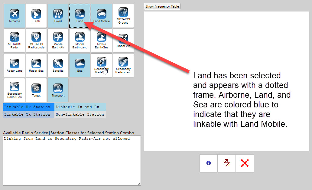
1. Select a station type icon from the station palette.
The selected station type is identified by a dotted frame, and other icons are colored based on the legend colors, to identify logical link relationships. In the image below, the Land Mobile station type has been selected, and Land, Airborne, and Sea are identified via color as being linkable with Land Mobile:
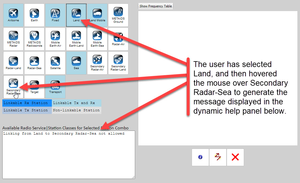
2. After a station type has been selected, check to see if the second station type you intend to select is linkable, by hovering over it.
The dynamic help panel, located in the bottom-left corner of the Diagram, will generate a message indicating whether the station type you are hovering over is linkable to the previously selected station type; if the link is permitted, the help panel will also identify radio service availability. In the image below, Land Mobile has been previously selected, and the user has then hovered over Secondary Radar-Sea.
3. Click on the selected station type icon, hold down the mouse button, drag over to the diagram, and release the button to place the icon into the diagram.
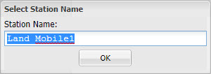
The icon can only be dragged and dropped inside the diagram. A green check mark icon appears when you are dragging the icon over the diagram to indicate that you are inside the permitted drop area. When the icon is being dragged over an area other than the diagram, a red warning icon appears to indicate that the icon cannot be dropped at its current screen location. When the station type icon is dropped into the drawing palette, a name selection box will automatically appear.
4. Enter a name and select  .
.
The system will not allow duplicate station names. The name will appear below the icon inside the drawing palette:
5. If you are diagramming a system with multiple station types (i.e., you are not diagramming a a system where the transmitting and the receiving station types are the same), the steps are the same.
Repeat steps 1-4 for any other stations that need to be included in the diagram.
6. For some systems, the same station type serves as both transmitter and receiver, in which case you would not need to select a secondary station icon.
To create a uni-link for a system where the transmitting and receiving station types are the same, click on the uni-link button  in the link control panel.
The button will turn red to indicate it has been selected. Then click on the station type receiving the link. If the link is permitted, the link will appear in the diagram: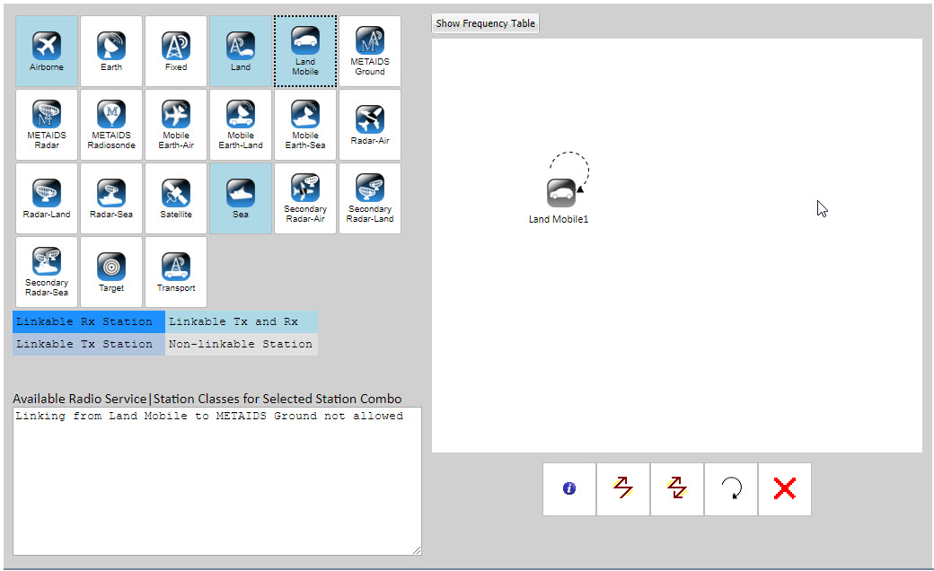
To indicate that it has been deselected, the button will no longer appear red. If the uni-link is not permitted, you will receive an error message such as the following:
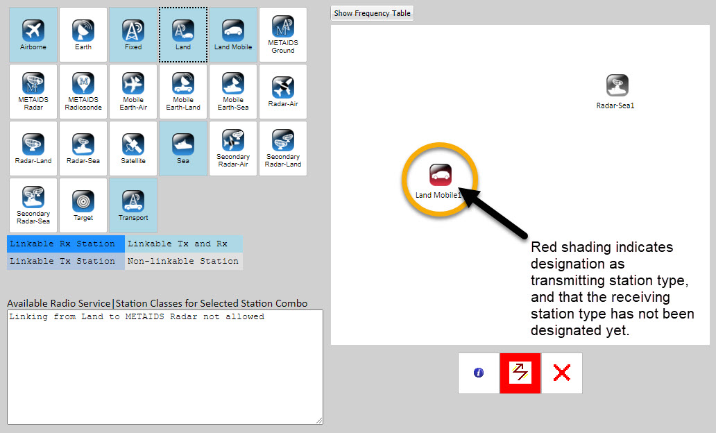
7. To create a standard link between two separate station types, click on the  link button in the link control panel.
The button will turn red to indicate it has been selected. Then click on the station type that will act as the transmitting station. As depicted in the image below, , the icon will turn red to indicate (a) the transmitting station type has been designated, but (b) the receiving station has not been indicated (i.e., has not been clicked on yet):
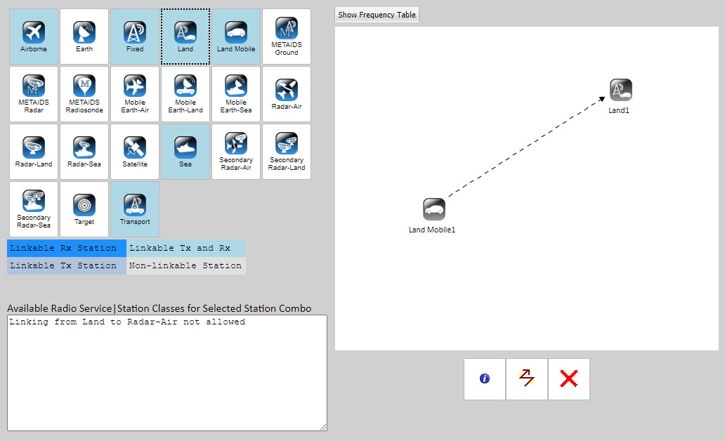
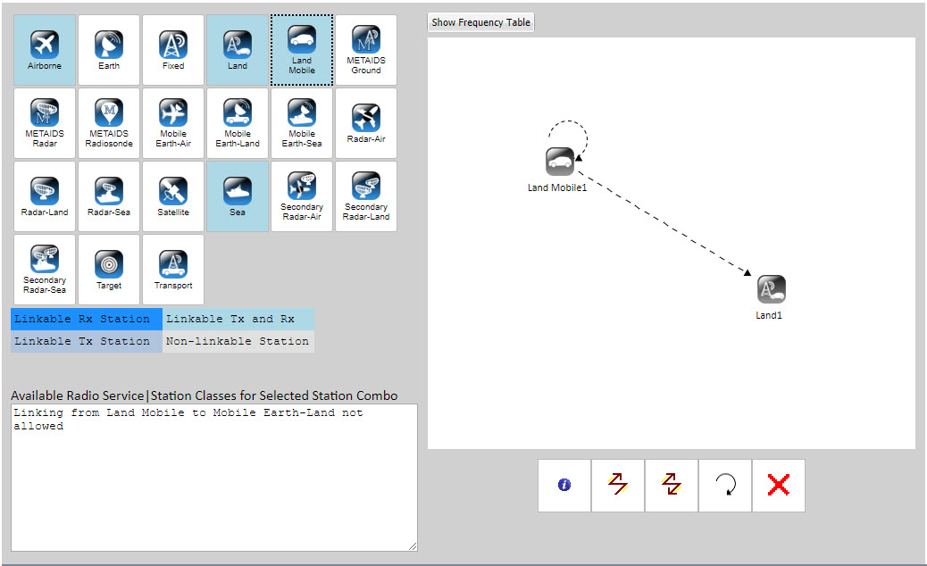
8. After you have identified the transmitting station type, click on the icon that you wish to designate as the receiving station type.
If a link is permissible, an arrow will appear on the screen with the arrow head pointing toward the receiving station type, and the transmitting station type icon will no longer appear red because the link creation action is now complete:
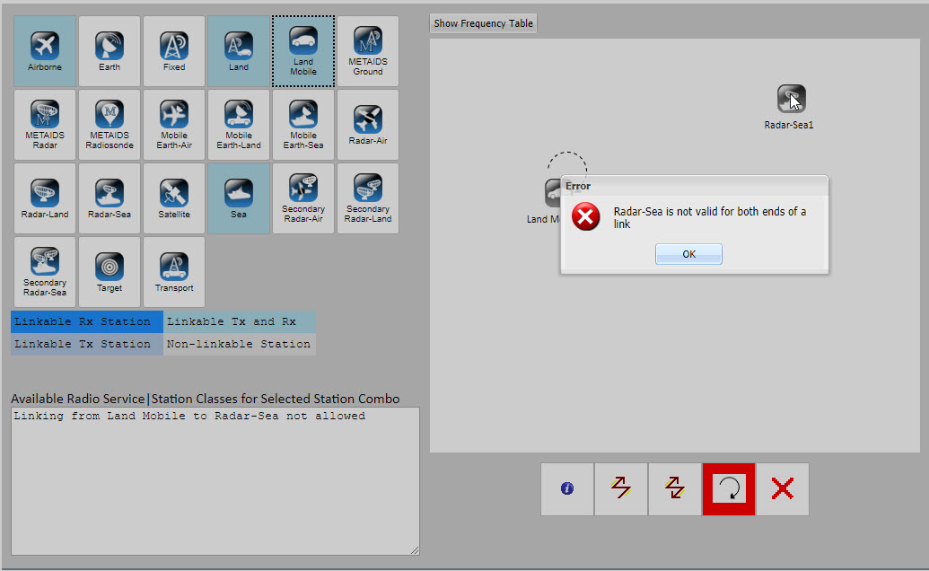
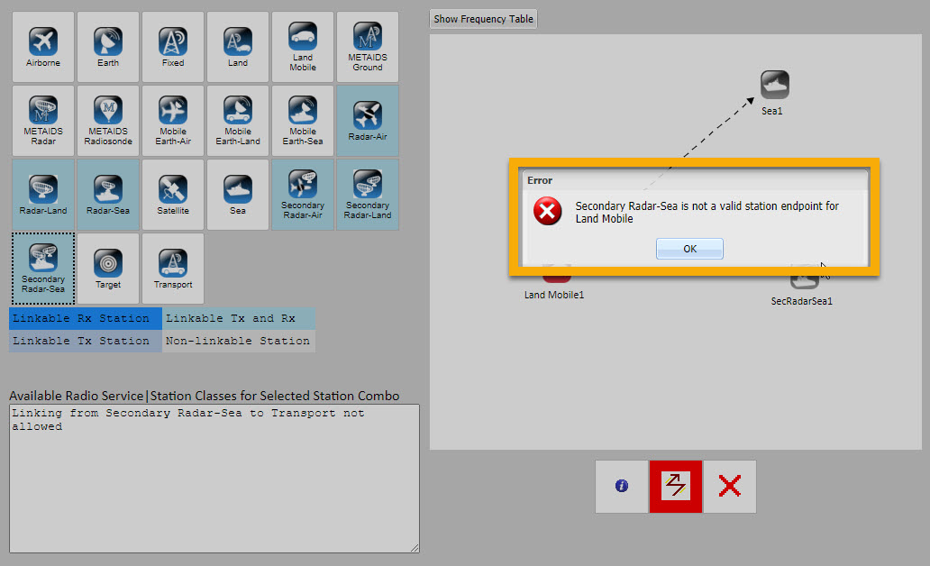
If the link is not permissible, an error message such as the following will appear:
When you select OK, the transmitting station type icon and link button remain red to indicate that the link creation action is not yet complete.
9. Complete as many links as are needed.
There are no limits to the amount of links you may create.
A link will appear as a dotted line until data entry for that link has been completed. After entering all the link data, users may return to the diagram. At that point the links will be drawn with solid lines.
10. A single station type icon in the diagram can receive multiple link types,
as demonstrated in the image below:
11. The order in which either station types or links are added to the drawing palette does not matter.
You may add the transmitting station type first, or the receiving station type first.
12. Station type icons and links may be deleted at any time.
Use the  button. The Delete Button will bring up a dialog box listing the diagram elements. Select the elements to delete and click the button.
13. When you are finished with the Diagram, select  .
.
System information diagrammed through the Diagram will impact some Editor fields, such as View Summary. Conversely, transmitter, receiver, and antenna information entered through the navigation panel will alter/update the configuration of the diagram.
To prevent the creation of invalid links, EL-CID Online Editor will not allow system type changes after the creation of the SID.
There are many Diagram work sequence scenarios due to the large number of diagram components. This help content is not intended to address all scenarios; instead, it provides principles to help the user understand the Diagram design logic. This understanding should then be applied to aid the user in completing specific diagram scenarios.
The dynamic help panel message responds to the most recent station that the user has hovered over. In the example below, if the user were to hover over Secondary Radar-Sea and then move the mouse pointer to a different area of the screen without moving over a different station icon, the dynamic help panel message would not change despite the fact that the user would no longer be hovering over Secondary Radar-Sea.
Once you have placed an icon into the diagram, you cannot drag and drop the icon to remove it from the diagram. To remove an icon from the diagram, you must click on the button and then identify the diagram component you wish to remove.
Note that stations and links can only be deleted from the Diagram page when first creating the diagram. After navigating away from the Diagram or when editing uploaded files, use the NTIA General Information or
If users click on the "Diagram" link in the Navigation Panel while working on a diagram, The Diagram page will reload. Recent changes may be lost.
If two stations are very close together in the diagram, the dotted link indicating incomplete data may appear solid. In this case, simply refresh the browser page, and the stations will spread out to give the link room to draw properly.
To deselect either the uni-link or bi-link buttons after they have been selected, simply click on the button a second time.